ladysi
Senior Member
- First Name
- Andrea
- Joined
- Jun 26, 2018
- Threads
- 21
- Messages
- 388
- Reaction score
- 421
- Location
- Minnesota
- Vehicle(s)
- 2018 civic si black sedan
- Vehicle Showcase
- 1
- Thread starter
- #1
Ok, so I originally purchased the Uniden R3 Official Hardwire (with mute button/alert led/power led) box with plans to cannibalize it for a momentary button/activity led to install into my center console.
https://www.amazon.com/Uniden-RDA-HDWKT-Detector-Hardwire-Button/dp/B07BBVC7JQ
So I took the time to rip it apart today:
To my surprise, THIS DIDN'T WORK. I checked all of the connections - the board with my modifications was outputting 11.5v, but not the 12 expected by the device. I am not sure why it didn't work, maybe my soldering iron overheated one of the transistors?
Anyways, for about 3 hours while I finished the other tasks on my car, I was worried that I had shorted my Uniden R3....a $400 mistake
I got home an hour ago and quickly grabbed my lighter power cable and tested the R3, lo and behold....it still worked! So I definitely fucked up the hardwire box's board in some way. I will post the pictures of the box teardown nonetheless in case any one else wants to take a stab at converting it.....
Pictures of failed attempt:


BUT, I WAS NOT SATISFIED. I decided to do some research on the pinout of the R3, looking at the pinout and few schematics for the "smart cable" (the lighter adapter cable that ships with the R3). To my surprise, the pinout and base schematic for the mute button and alert led are STUPID FUCKING SIMPLE.
If you are interested in the details of the electronics, checkout:
https://www.rdforum.org/index.php?threads/74522/#post-1059916
The schematic in question:
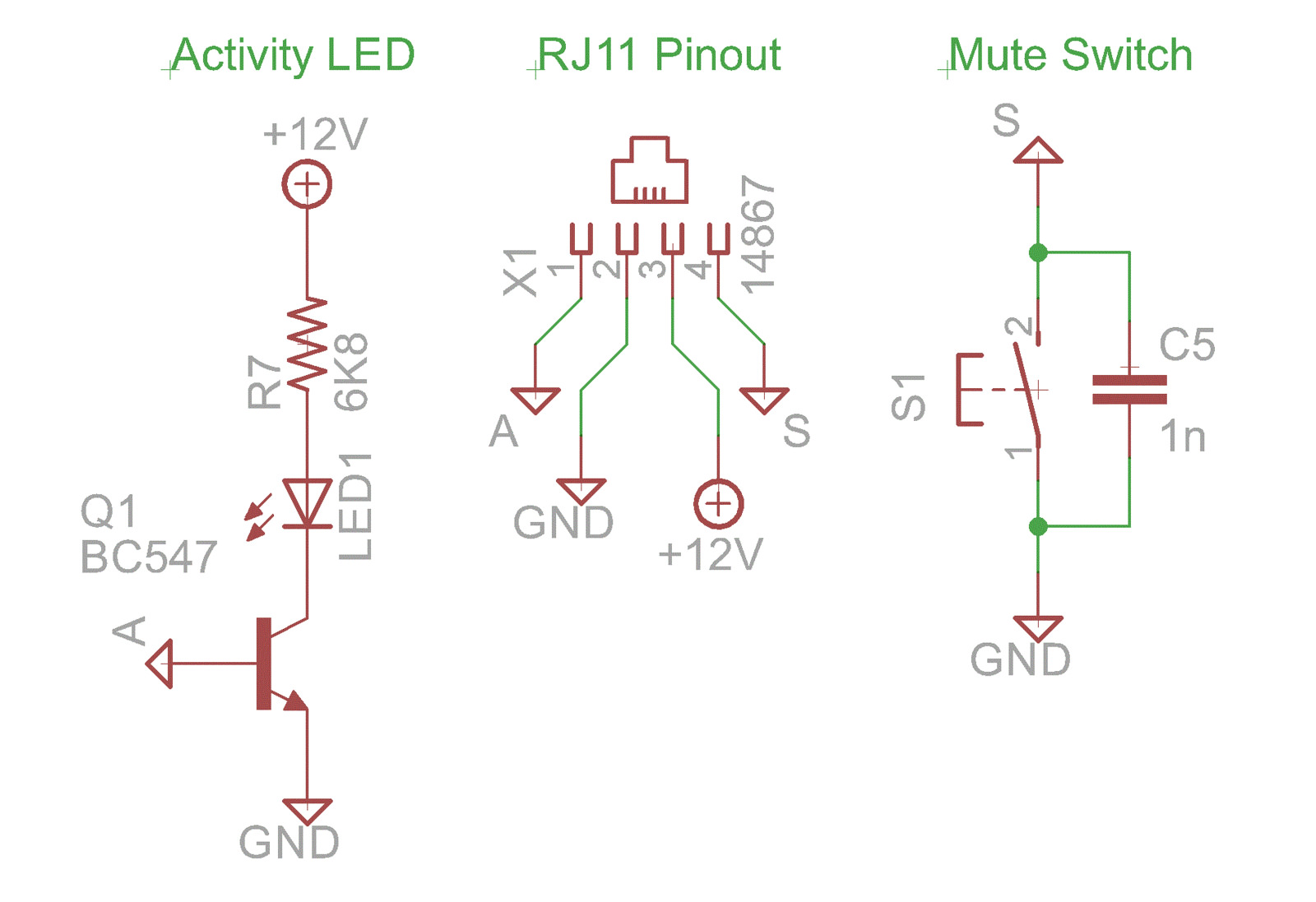
Basically, the 12v and ground are straight forward. The mute button as well - it just shorts to ground for both long (dimming option) and short (mute) presses.
The alert LED is a tiny bit more complicated - it has a transistor circuit to invert the high and the low for the led - basically, the alert pin always has power unless there is an alert. So if you are fine with the led staying on and blinking off during an alert, then the wiring is STUPID FUCKING SIMPLE. If you only want it to flash on when there is an alert, then you need to use an NPN transistor, or build an inversion circuit.
In my case, blinking off during an alert is enough for me. So tomorrow I will fix my hardwiring setup and connect my mute button/led.
The button from adadfruit:
https://www.adafruit.com/product/559
The button led supports 3v to 6v, since the alert pin on the uniden is 3.3v, it should be fine as long as there is not too much voltage drop.
I tested it tonight on another similar (yet smaller button), and it works just as expected. My test button:
button pin 1: switch input connected to uniden pin 4 (S)
button pin 2: switch output connected to uniden pin 2 (G)
button pin 3: led pos connected to uniden pin 1 (A)
button pin 4: led neg connected to uniden pin 2 (G)
Video of test:
Button Install:
I was already pulling the center console and shifter apart for the console illumination mod today, so I figured I would wire in my button. Below are some pics of the button and harness - I think I failed to get pics of the harness actually being installed into the center console, so I may take those another time and follow up on this thread.
Basically:
I will update this thread once I finish the wiring in the next day or two now that I know the STUPID FUCKING EASY way to do it
Picture of the Process above:


Thanks for reading about my silly aggressive hardwire mod failure, my near miss with shorting out the uniden r3, and my redemption later this evening (including a working test).
Cheers mates.
https://www.amazon.com/Uniden-RDA-HDWKT-Detector-Hardwire-Button/dp/B07BBVC7JQ
So I took the time to rip it apart today:
- Dremmel the box open.
- Remove the mute button and the activity led.
- Solder leads to each connection (led pos, led neg, button input, button output).
- Heat shrink and liquid electrical tape.
- File the case edges from the dremmel burrs, put it back together, and hot glue it.
To my surprise, THIS DIDN'T WORK. I checked all of the connections - the board with my modifications was outputting 11.5v, but not the 12 expected by the device. I am not sure why it didn't work, maybe my soldering iron overheated one of the transistors?
Anyways, for about 3 hours while I finished the other tasks on my car, I was worried that I had shorted my Uniden R3....a $400 mistake
I got home an hour ago and quickly grabbed my lighter power cable and tested the R3, lo and behold....it still worked! So I definitely fucked up the hardwire box's board in some way. I will post the pictures of the box teardown nonetheless in case any one else wants to take a stab at converting it.....
Pictures of failed attempt:
BUT, I WAS NOT SATISFIED. I decided to do some research on the pinout of the R3, looking at the pinout and few schematics for the "smart cable" (the lighter adapter cable that ships with the R3). To my surprise, the pinout and base schematic for the mute button and alert led are STUPID FUCKING SIMPLE.
If you are interested in the details of the electronics, checkout:
https://www.rdforum.org/index.php?threads/74522/#post-1059916
The schematic in question:
Basically, the 12v and ground are straight forward. The mute button as well - it just shorts to ground for both long (dimming option) and short (mute) presses.
The alert LED is a tiny bit more complicated - it has a transistor circuit to invert the high and the low for the led - basically, the alert pin always has power unless there is an alert. So if you are fine with the led staying on and blinking off during an alert, then the wiring is STUPID FUCKING SIMPLE. If you only want it to flash on when there is an alert, then you need to use an NPN transistor, or build an inversion circuit.
In my case, blinking off during an alert is enough for me. So tomorrow I will fix my hardwiring setup and connect my mute button/led.
The button from adadfruit:
https://www.adafruit.com/product/559
The button led supports 3v to 6v, since the alert pin on the uniden is 3.3v, it should be fine as long as there is not too much voltage drop.
I tested it tonight on another similar (yet smaller button), and it works just as expected. My test button:
button pin 1: switch input connected to uniden pin 4 (S)
button pin 2: switch output connected to uniden pin 2 (G)
button pin 3: led pos connected to uniden pin 1 (A)
button pin 4: led neg connected to uniden pin 2 (G)
Video of test:
Button Install:
I was already pulling the center console and shifter apart for the console illumination mod today, so I figured I would wire in my button. Below are some pics of the button and harness - I think I failed to get pics of the harness actually being installed into the center console, so I may take those another time and follow up on this thread.
Basically:
- Center console disassembled and the shifter panel with a button blank removed.
- The button blank was drilled out.was drilled out and the button was inserted
- Four wires were soldered to the button, heat shrunk, and liquid electrical taped (led pos=red, led neg=black, switch input=blue, switch output=green).
- The wires were then soldered and heat shrunk to harness (8pin video card power connector I had lying around - 4 pins for expansion!).
- Long wires were soldered to the other side of the harness.
- The car side of the harness was secured in the shifter compartment and zip tied to the "Sport" button harness.
- I ran the cables to the drivers side of the shifter compartment and zip tied the cable to the auto harness cable and then ran it down through the bottom of the shifter compartment into the canyon between the seat and the center console.
I will update this thread once I finish the wiring in the next day or two now that I know the STUPID FUCKING EASY way to do it
Picture of the Process above:
Thanks for reading about my silly aggressive hardwire mod failure, my near miss with shorting out the uniden r3, and my redemption later this evening (including a working test).
Cheers mates.
Last edited:
